Detailed Information
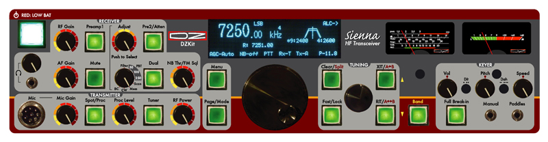
Click HERE for the block diagram of the Sienna. Front panel controls are grouped by function:
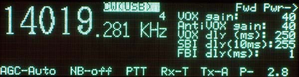
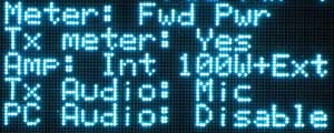
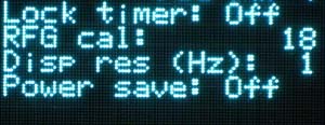
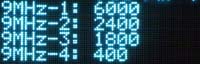
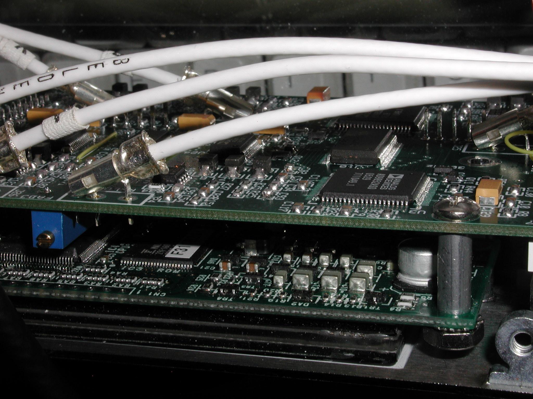
TRANSMITTER: Mic jack, Mic gain, RF Speech processor, RF Proc level, Tuner, RF Power MENU: Pressing the "Menu" button displays a menu on the right side of the display. Rotating the small tuning knob button changes pages, forward or backward. Rotating the large knob either direction selects and highlights a menu item and then rotating the small knob right or left changes its value. Pressing the Page/Mode button when not in MENU mode enables the small knob to rotate forward or backward through the modes (CW-USB, CW-LSB, USB, LSB, AM, FM, Dig-USB, Dig-LSB). Menu items settable from the first menu are Mode, AGC, NB, PTT/VOX, Receive Antenna and Transmit antenna, all of which remain on the screen at all times. In the upper right corner of the display is the current Transmit Meter selection. In the lower right corner is the RF Power output setting, which is controlled by the RF Power control in the transmitter section. There's no cryptic gobbledegook in the menus, just easy to understand text. Here are four examples. On the left, the main display shows frequency, selected VFOA memory (1-5), mode (CW(USB) in this case, highlighted in inverse to show that it is the item currently selected), AGC setting, Noise Blanker setting, PTT/VOX, Receive antenna (T= Transmit, R=Receive antenna), Transmit antenna (A or B), and Power level in Watts (here set to 2.8W). The selected menu in the leftmost picture allows changes to the VOX gain, AntiVOX gain, VOX delay, Semi-Break-In (SBI) delay, and Full-Break-In (FBI) delay. The other three pictures show only the right half of the display. There are 16 pages of menu items that can be stepped through, all using straightforward text. The far right picture shows the menu that is used to enter the crystal filter bandwidths that have been installed in the four 9MHz IF slots. All these settings are saved in non-volatile memory when power is off. TUNING: The large knob changes the main frequency by 1Hz if displaying 1Hz resolution, or by 10Hz if displaying 10Hz resolution (settable in a menu option). If "Fast" is on, the display changes by 100Hz or 1KHz respectively. The small knob changes the frequency by 10Hz if displaying 1Hz resolution, or 100Hz if displaying 10Hz resolution. If "Fast" is on, the display changes by 1KHz or 10KHz respectively. If the Fast button is pushed and then no activity occurs for a period of time (off, 10s, 30s, 60s settable in a menu option), the dials are locked and "Lock" appears in the display (top row). Pressing CLEAR when not in RIT/XIT mode selects SPLIT mode. In SPLIT mode, the XIT button becomes A>B, and the RIT button becomes A<>B. In SPLIT mode, as with XIT, the small knob controls the transmit frequency while the large knob controls the receive frequency. There are FIVE VFO's per band, and each VFO remembers the last frequency, filter, preamp, attenuator, and mode settings. The external keypad can be used to select Dual, Split, A>B, A<>B, A>M, M>A, Memory Up, Memory Down, Scratchpad Store, Scratchpad Recall, or direct band entry mode. In Memory mode, the bottom right section of the display shows the current memory frequency and mode. The main tuning tuning knob is machined aluminum, with a finger dimple, and is attached to an extremely smooth (and very expensive!) optically-encoded rotary pulse generator, giving the rig a nice "feel" as you tune around. The small knob is hard plastic with a metal insert, also attached to an RPG. BAND: If "Band" is pushed, rotating the large knob changes the band and selects the last used frequency on the last used VFO memory (of five available per band, as shown by the small number above the "z" in kHz). Rotating the small knob changes to the last used frequency on the next VFO memory and increments or decrements the small number. Also, in BAND mode, the RIT button serves as previous VFO memory and the XIT button serves as next VFO memory. Band Memories: KEYER: Sidetone volume, Pitch and Keyer speed are set by the three black knobs. Between them are screwdriver adjustable Dot spacing and Dash spacing pots. Nylon hole plugs (not shown) are included in the kit to cover these openings if desired when not in use. Full or Semi break-in can be selected, with independent control of the time delays for both modes settable in a menu item. Keyer paddles and a straight key or other keying device are active simultaneously from minijacks on the front or back panel. Iambic A, Iambic B and Ultimatic modes are selectable from the menu. METERS: The right meter is an S-meter and the left one is a Transmit meter that shows Fwd and Reflected Power, SWR, ALC, RF Compression, PA Current, Driver Current and PA Voltage. You asked for a new rig notbuilt overseas that had the features you want at a competitive price. Tall order! But the engineers at the DZ Co. put their noses to the grindstone and came up with a rig with these exciting features: Kit form means it’s not outsourced! It's built wherever you live, because you build it! And we don't mean that you snap together preassembled boards (well, OK, four of the 12 boards are completely built due to the need for a lot of SMT parts just to get everything to fit!). You build almost everything and wind your own toroids too. It's a lot of work, but we think you'll have a lot more fun that way and be considerably more proud of your accomplishment when you're done. DESIGN PHILOSOPHY The Sienna was designed to accomplish two major goals: 1) Offer a nice looking and well-designed kit, and 2) Offer features not found in any radio for the price. To that end, we designed a rig that has just enough controls on the front to be easy for big fingers to use, and we eliminated some buttons that many people have come to expect, such as a direct frequency entry and numeric keypad, memories, band switches and AGC controls. These all take up valuable real estate, forcing buttons to be small with confusing functionality per button. But we provided for these by supporting use of the Yaesu FH-1, FH-2 or similar external keypad, which adds 12 buttons for a variety of features. Buttons. Some functions, such as AGC, we made automatic based on mode and provided a menu selection. Bandswitching was accomplished by using a single "Band" button, allowing the main tuning knob or the RIT/XIT buttons to change bands rapidly, up or down, and the RIT/XIT knob to select one of the five VFO memories on the selected band. When not in "Band" mode, the RIT/XIT knob functions as a coarse frequency control when RIT/XIT are inactive. And both knobs operate in a coarser mode yet when the "Fast" button is pushed. The result is extremely agile control of frequency without using a lot of buttons. When you add the Yaesu FH-1, FH-2 or equivalent keypad (a simple 12-button, 12 resistor design that you can also make yourself), you also get access to the 86 general purpose memories and direct band entry for all bands including 60M. Other button-intensive functions we left to the embedded PC. We figure that the PC offers so much flexibility that intensive alphanumeric operations belong there, not on the front panel. Yes, the PC adds cost, but it also offers built-in functionality that an external PC can't touch, such as elimination of a rig interface box and fan noise, not to mention making it easier to transport! It also adds digital modes using standard software (as opposed to funky "scrolling displays" and use of the CW key to send digital modes!), availability of lots of free or inexpensive software, ability to control the radio remotely without having to install software (called a "web server"), audio DSP, digital voice recording and playback and so much more. All of these features take up a lot of code space in a typical microprocessor when they can be added in software much more easily (and upgraded easily as newer software becomes available). It made it possible to put only the functions you use the most on the front panel. It also cleared space for an analog meter, something everyone has told us they want. Analog meters are very large and expensive, which is why you see so many rigs implementing them digitally. But there's something warm and comforting about a backlit analog meter. We use a Hoyt 811-T 100uA meter with a custom DZ faceplate. Receiver What about the circuitry? Sienna employs a triple conversion receiver design using a 70.0 or 70.455MHz first IF, which allowed us to offer the excellent roofing filter made for the Yaesu FT-1000MP by Inrad (6-pole/4.5KHz) to really improve dynamic range. Because the receiver uses upconversion (0-30MHz is converted to a higher frequency), the DDS oscillators are more complex, which adds cost. BUT, it also provides full frequency coverage from 500KHz to 30MHz with no dead spots. Radios with first IF frequencies below 30MHz must, by nature, have a dead spot around that IF, whether it's 9MHz (Ten-Tec Orion), or 4.915 (Elecraft K2) or 8.215MHz (Elecraft K3). They may say they have a general coverage receiver, but they exclude areas near the IF. Sienna does not suffer from that restriction. The compromise is that we can't offer an extremely narrow roofing filter, because it would cost too much. However, we've measured >105dB of blocking dynamic range with signal separation of 1KHz from the desired signal, when the 400Hz IF filters are selected at the 9MHz and 455KHz IF frequencies and over 125dB at separations > 5kHz. Sienna allows use of four selectable Inrad crystal or Collins mechanical filters for the 2nd and 3rd IF, with one included standard at each IF. A "Hang AGC" is implemented at the 455KHz IF, allowing fast attack from the IF signal with selectable decay based on audio level. The AGC signal is buffered and used as a control signal for the BF-992 dual-gate MOSFET amplifiers used at the first and second IF, and the MC1350 used at the 3rd IF. A separate AGC gain calibration menu item allows you to set the AGC gain for AM separately. We've spent a good part of the five-year development time of this radio working on the AGC and we think you'll like it. Here's a bottom view of the IF filter access:
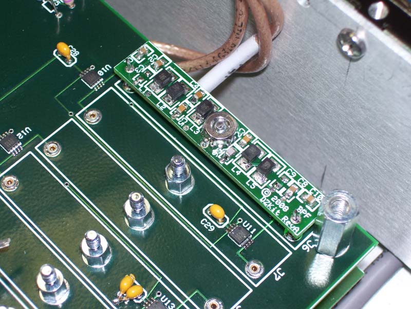
Receive bandpass filters are implemented using surface mount inductors and chip capacitors, and each one is switched in via Hittite HMC349 GaAsFET SPDT switches. These devices have an IP3 of +50dBm and 70dB of channel-to-channel isolation, providing plenty of margin for large signals with low distortion. And exclusively with the DZKit Sienna, you can bypass these filters, resulting in about 5dB less loss. The increased bandwidth going into the receiver can cause higher IMD and more out-of-band mixing products, so it's not something you want to keep enabled, but when you're trying to extract the last dB of signal from a weak station, it can help. We call it "PassiveSignalBoost (PSB)TM". There are 11 bands of these filters covering 500KHz-30MHz for the receiver, and 10 for the transmitter, covering the 10 ham bands in that frequency range (and since they snap in, we can make them handle any transmit frequency range you need). The transmitter does not share the same bandpass filters as the receiver (a requirement for full duplex operation), so there's no effect on transmit performance when using PSB. These filters snap into the transmitter board and the receiver's "RXBPF" board. Here's a photo: Two RF preamps can be switched in after the bandpass filters. These utilize 2N5109 NPN transistors. Each provides about 10dB of low-noise gain. There is also a 10dB attenuator accessible from the Pre2/Atten button on the front panel -- with Pre1 off, press Pre2/Atten for 10dB of attenuaton. A noise blanker with a variable threshold and three selectable pulse widths is located after the 2nd mixer, at 9MHz, prior to the crystal filters, to catch as much wideband noise as possible. This NB, like most NB's, is designed to eliminate strong impulse-type noise, such as that caused by light dimmers, automobile ignitions or electric fences. It is not intended to conquer the Russian Woodpecker or other low-level noise. Secondary Receiver/Panadapter Many hams like to use secondary receivers as "spotting" receivers, which is very useful in contests for finding new multipliers by listening to one receiver in one ear while operating on another frequency and listening in the other ear. A secondary receiver is also useful for comparing antenna performance - use the main antenna on one receiver while listening to another antenna on the other receiver. Unfortunately, it can be very difficult to optimize both receivers for best dynamic range, IMD and sensitivity when both are operating in the same enclosure and having simultaneously operating local oscillators. The secondary receiver also usually suffers from a lack of independent front panel controls due to space and cost concerns. Even some of the very expensive rigs have eliminated an internal secondary receiver, and other manufacturers are struggling with their designs too. We actually had a secondary receiver in the Sienna during its early design phases, but we removed it for just these reasons. It was too big a compromise.Instead, we chose to support the addition of an inexpensive external secondary receiver that can be controlled by a PC, thus giving you complete control over that receiver with an independent set of controls, and eliminating any performance issues due to cramming too much inside one rig. You can use either an additional receive-only Sienna (S-100 or SF-100 with a PC) or an RFSpace SDR-IQ. The latter is a very good receiver that Sienna can control directly from a PC. The SDR-IQ also can be used as a spectrum display (panadapter) by connecting it to the 455 kHz IF output . The secondary receiver's speaker output can be fed into the line-in jack on Sienna's back panel, and then fed to the left speaker when the front panel "dual" button is pushed, with Sienna's own internal receiver going to the right speaker. We think this is a much better way to handle secondary receive capabilities. If you don't use this type of functionality, you don't have to pay for the needed infrastructure inside the rig and you get a much better receiver that's easier to control too. All circuitry is tried and true analog design. We purposely chose not to use IF DSP (digital signal processing) or SDR (software-defined radio) techniques which are still an evolving art form. DSP means that intermediate frequency signals (usually at a low IF such as 15KHz) can be processed digitally in special high speed chips that implement filter functions in software. SDR means that many of the radio's mixers, oscillators, amplifiers and filters are implemented in software, using math routines. Typically, a signal is sampled at a very high rate with an A/D converter, and the resulting samples are then run through algorithms to, say, create the sum and difference products after multiplication by a cosine function, or to implement a bandpass filter. The demodulated signal is then converted back into a digital stream that is fed to a digital to analog converter (DAC) which drives the speakers. The transmitter can also be implemented in software, at least up to the power output stages. As a sampled system, care must be taken to avoid aliasing effects. One side-effect of SDR is that since so much functionality is done in firmware (software that is stored in read-only-memory), it can easily fall into the software trap of being "never done", forcing you to download new code periodically until the designer "gets it right". Modern transceivers, including Sienna, allow the user to download new firmware into the microprocessor. But Sienna's firmware is only used to control the analog hardware, not to implement the bulk of the radio. As a result, when it is shipped, all functions are working and tested. You will never have to download new firmware to get features that you paid for months earlier. We believe that firmware updates should be used to fix bugs or add new features not previously advertised, not to complete the radio's advertised features. We will not take your money and then ship you an unfinished product. What difference is there between a DSP operating inside a custom processor at 15KHz (barely above the audio range) and one operating inside a PC at 2KHz? Not much really. There's one less mixer in the way with IF DSP. But baseband audio is as good a place as any to do DSP, and the PC can execute much, much faster than the microprocessors used in custom DSP implementations. Yes, sound cards currently have only 16 bits of dynamic range compared to the 20-24 bits typically used in custom DSP implementations, but you'll be impressed with how good a job that actually does. And as High-Def sound cards become commonplace (already starting to happen), with up to 32 bit processing, this objection will simply go away. We didn't want to waste our time, or yours, developing yet another set of DSP algorithms in custom chips when they're commonly available on the PC. What about the fact that audio DSP operates on the signal after the AGC? You can get around this problem by turning AGC off in Sienna's hardware and turning on the AGC function in the audio DSP program. Transmitter/DDS The transmitter uses a completely separate set of DDS oscillators and bandpass filters, allowing full duplex operation when the receive antenna is used. Since the oscillators are separate, we use one of them to provide a known frequency/amplitude RF signal during receiver calibration. All DDS oscillators are fed by a custom 30MHz +/-1PPM temperature compensated crystal oscillator (TCXO). This oscillator has a ten-turn pot on it to allow its frequency to be tweaked very precisely. In this photo, you can see one of the six Analog Devices DDS chips used in the Sienna. The AD9852 DDS used in the VFO and the 2nd IF have built-in PLL's on the reference clock. Internal clock speed is 300MHz, which along with the 48 bit programming data, allows very fine frequency resolution. Audio can be routed from the mic to the PC for processing. PC audio can then be fed into the transmitter, so you can have processed mic or soundcard output for digital modes. As digital audio becomes all the rage, Sienna will easily handle the task, since the digital audio can be generated in the internal PC and fed to the transmitter. The selected audio can also be processed using an analog RF speech processor that operates at the transmitter's 10.7MHz IF frequency. 6M Many rigs are offering 6M coverage these days. We chose not to. Why? Most of you have said it would be "nice", but not required in a rig that's mainly going to be used for HF. Sorry if 6M is your favorite band, but any 6M coverage we added would be a compromise and we do not want to offer compromises (see above comments on the secondary receiver). When we offer a 6M rig, it will be a really good one. Besides, you can add a 6M transverter to the Sienna quite easily. Many have told us that they don't want to pay for features they will never use. 6M is one of those features that can easily add cost to the radio, so we chose to go the transverter route here allowing you to add it only if you really want it. Made in U.S.A. With very few exceptions, Sienna is a "Made in the U.S.A." product. We think you'll appreciate our decision to use U.S. manufacturing, despite occasionally higher costs. Our chassis is made in Golden, CO by a top-notch family-run business that makes things for the likes of Hewlett-Packard (now Agilent Technologies) and other well-known companies. Our PC boards are made at various U.S. shops. Cable assemblies are made in Cheyenne, WY and Canada. Electronic parts of course come from a variety of countries, but we use American distributors wherever possible. We also favor woman-owned small businesses such as Kreger Components, a source of many of our toroids. The front panel Lexan part is made in Illinois by BW Industries. We believe in America and American manufacturing. We relented on one thing -- the embedded PC is made in Taiwan, but we buy them through American reps. Service
True Kits The DZKit founders are all dyed-in-the-wool hobbyists. We built a lot of Heathkits in the "good ol' days" and we want you to have that kind of fun too. Even though SMT continues to make through-hole boards more and more old-fashioned, the parts are still available. In fact, we've had some SMT parts go obsolete faster than older through-hole parts! We've tried very hard to use the right mix of SMT where it's needed most, while offering you lots of soldering and assembly too. We've been asked, "who did you make this for?" The answer is, we made it for ourselves, and we think we're a lot like you. We're not hardcore contesters or DXers, although we dabble at that stuff. No, we like to experiment, ragchew, operate radios and have fun. We wanted something that looked nice, had some cool features not available elsewhere and that we could offer to you in kit form. Look at the photo below of a completely assembled Sienna and think about this: You get to build almost the whole thing. Only a few critical subassemblies are preassembled and tested. Can you build something this complex? You bet you can! Customer Service We're committed to great customer service in the finest tradition of Heathkit in its glory days. We're small enough to be able to listen to our customers and react quickly to wants, whether they are new features on existing products, or all new products. Let us know what you want. We'll do our best to make it happen. |
And look at these other DZKit innovations!
High-intercept-point GaAsFET switches in the bandpass filter assembly, for a dramatic space reduction and general frequency coverage. Direct Digital Synthesis of all receive and transmit oscillators, resulting in a 70.455MHz 1st IF, 9 MHz 2nd IF, 455 KHz 3rd IF and BFO for the receiver. Transmitter has a separate 10.7MHz IF and 12-40MHz VFO. Master reference oscillator is a low phase-noise +/-1 ppm, 30 MHz TCXO. If you're from the government, call us if you'd like to use a 0.2ppm OCXO (adds approx $450, and is subject to a minimum order quantity). 256x64 Vacuum Fluorescent Blue-Green Graphics Display – no indecipherable 7-segment gobbledygook, and no expensive built-in non-upgradeable LCD display (which also makes a rig physically bigger than it needs to be). You decide if you want the expense of a nice color display when you use the embedded PC with an external VGA of whatever size you want – a cheap 14" CRT or a widescreen 60" HDTV receiver with VGA inputs! Or even a battery-operated VGA like the Xenarc shown on our datasheet page. Pre-sorted parts! Think about how most kit companies provide parts – they dump them in a bag and let you sort them. We figure that since we know what we’re pulling from stock, we ought to put the parts in pre-labeled bags – one per component value, when there's any ambiguity in component values. Having a little trouble reading the resistor color code or the tiny marks on a small ceramic disk cap? Not any more! Just find the right bag! We’ve thought a lot about how to make your kit-building experience fun and hassle-free. We figure that the easier we make your experience, the more likely you won't need support, and that saves us time and helps us keep the price as low as possible. A manual that you will want to save. Our manuals are the same quality as the ones you may remember from long ago. Detailed drawings, parts lists, pictorials, step-by-step instructions, troubleshooting hints and more. You can download it free off our web site (or send $30 for a printed copy). The Sienna assembly manual can be downloaded from our catalog page. Years from now, you’ll be able to sell your Sienna more easily since the buyer will know that the rig is serviceable and "restorable" with the help of the manual. That is, assuming you want to part with it. By the way, we've added some modern improvements to our manuals. If you have a PC, or if you ordered the internal PC, you'll like what we've added -- the ability to load the component locator file for each board (on an external PC or even right on the embedded one in the rig as you build it!) and then simply type ctrl-F to search for a part. It's much quicker (not to mention easier on us as we make the manuals) and easier than the old printed method. Our beta testers loved it. Even if you're not too computer savvy, you'll pick it up quite easily. |
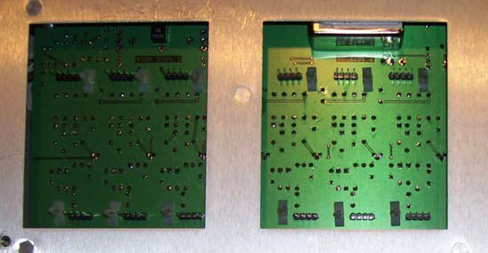
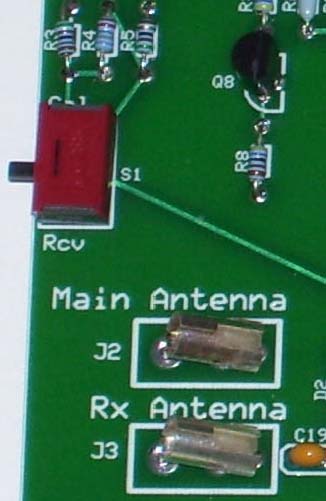 One of the hallmarks of kitbuilding has always been the ability to work on your radio yourself to avoid the hassle and expense of returning the product for service or alignment. One is shown here -- flipping this switch on the "RxBPF" board and connecting the transmitter's local oscillator signal at 10.7MHz to the main or receive antenna jack feeds an S9 signal into the receiver, allowing you to cal the S-meter. By connecting the output to any shortwave receiver, you can also test the preamps, attenuator and antenna inputs before stacking the receiver board on top.
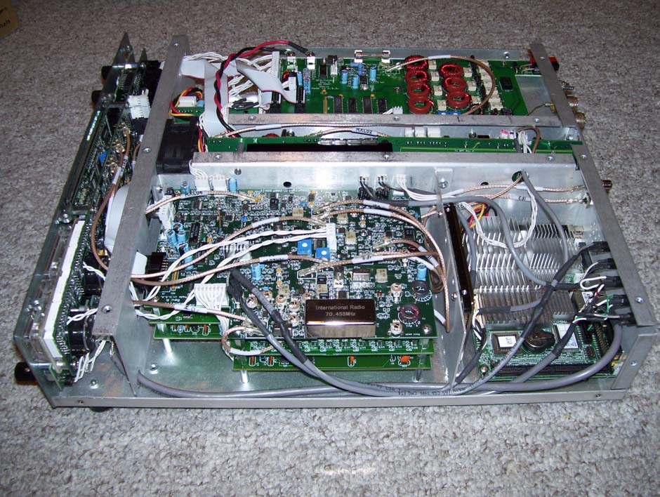
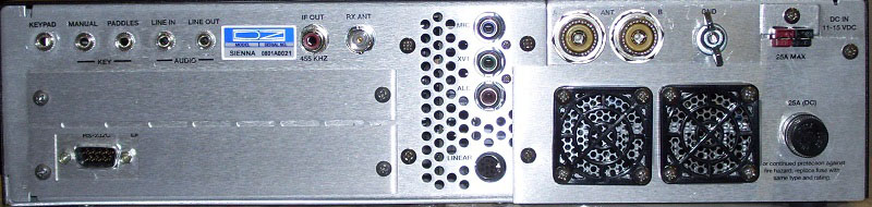
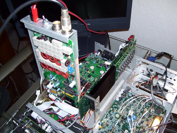 Sienna also has excellent built-in servicing capabilities. The picture below shows two such features. When the unit is bolted together, the tuner and dc power distribution board ("DCD/Tuner") sits above the 100W power amplifier. To get at the amplifier, the tray holding the DCD/Tuner can be rotated up and locked into a vertical position. And the transmitter can be moved up out of its center compartment for easy access to its components.